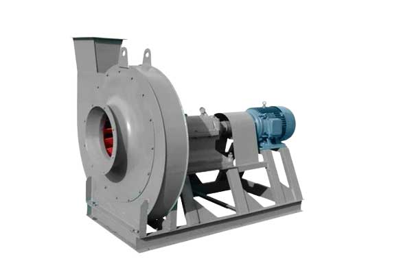
Forced draft fans typically suck in gas and blow it outwards and are mainly used for pressurization, ventilation, and air supply in workplaces, such as workshop exhaust fans and paint booth exhaust fans. Induced draft fans, on the other hand, bring gas from the outside into the equipment and are commonly used in boilers, burners, and smoke treatment, such as the forced draft fan in power plants and chimney exhaust fans. Although the working principles and application fields of these two types of fans are different, they are both important industrial equipment.
The G series and Y series centrifugal blowers and induced draft fans are characterized by high efficiency, low noise, and high strength. The FDF conveys air, with a maximum temperature not exceeding 80℃. The IDF conveys flue gas, with a maximum temperature of 250℃.
Before the induced draft fan, a dust removal device with an efficiency not less than 85% must be installed to reduce the dust content in the flue gas entering the fan and improve the service life of the fan.
Both the forced draft fan and induced draft fan have a single suction inlet and are available in seven different sizes: No. 8, 9, 10, 11, 11.2, 12.5, 14, and 16. Each type of fan can be made into both right-hand and left-hand rotation. When viewed from the end of the motor, if the impeller rotates clockwise, it is called a right-hand fan and is represented by "R"; if the impeller rotates counterclockwise, it is called a left-hand fan and is represented by "L".
The exit position of the fan is represented by the angle of the air outlet of the casing. Both "R" and "L" fans can be made into six different angles: 0°, 45°, 90°, 135°, 180°, and 225°.
The transmission mode of the fans is all D-type, and the connection between the motor and the fan is through an elastic coupling direct drive. These two types of fans are mainly composed of impeller, casing, inlet, regulating door, and transmission group.
The impeller is welded with 12 backward-inclined airfoil-shaped blades between the arched cone-shaped wheel cover and the flat disk. The impeller of the induced draft fan uses a solid body at the head of the blades and adds wear-resistant material welding at the easily worn parts to improve the service life of the blades. The impellers are all tested for static and dynamic balance to ensure smooth operation.
The casing is a volute body welded with ordinary steel plates. The casing of the single suction fan is made into two different forms: the №8-12.5 casing is made into an integral structure, and the quarter of the casing of the №14 and 16 fans can be removed. For the induced draft fan, there is an ash door above the volute plate, and the plate is appropriately thickened to prevent smoke and ash wear and prolong service life.
The inlet is a convergent streamline integral structure, which is fixed on the inlet side of the casing with bolts.
The regulating door is a device used to adjust the air volume of the fan. The №8-12.5 fans are composed of 13 flower-shaped blades installed axially in front of the inlet. Due to the external transmission structure, they are flexible and convenient to rotate. The adjustment range is from 90° (fully closed) to 0° (fully open). The position of the regulating door handle, viewed from the inlet direction, is on the right side. For right-handed fans, pushing the handle from bottom to top is from fully closed to fully open. For left-handed fans, pulling the handle from top to bottom is from fully closed to fully open. To ensure the normal operation of each part of the regulating door, good lubrication is necessary. For the regulating door of the blower, calcium-sodium-based grease is used for lubrication. For the induced draft fan, due to the high gas temperature, molybdenum sulfide high-temperature (260℃) grease is used, which can ensure lubrication during high-temperature operation.
The transmission group uses a D-type transmission mode. It is composed of a main shaft, bearing box, coupling, and other components. The main shaft is made of high-quality steel. It uses a rolling bearing water-cooled integral bearing box. Therefore, it is necessary to install a water supply pipe, and the water consumption varies depending on the environmental temperature, generally considered as 0.5~1 m3/h. The bearing box is equipped with a thermometer and oil level indicator. The lubricating oil uses No. 30 mechanical oil, and the oil inlet volume is determined according to the oil level marking requirements.


